Why make a Mute Pedal?
Have you ever been in a meeting and you are suddenly put on the spot and need to talk? Or maybe you have some background noise and need to mute yourself but you are in the middle of something and don’t want to tab out of what you are doing? Well, that’s where a mute pedal comes in; it lets you mute and unmute yourself with minimal effort and doesn’t interfere with any other keyboard shortcuts as it uses the F13 key (yes, there are more F# keys than just 1-12).
How I approached the problem.
Step 1: What to do first
My steps were to figure out what I wanted, what material I already had, and how I wanted to make it. The first 2 steps were pretty easy to answer as I wanted a pedal that I can push with my foot and was big enough that I would not have to worry about missing it with my foot. As for material, I have an extra pro-micro that I had leftover from a previous project, some extra keyboard switches, some wire, a 3D printer, and a soldering iron.
Step 2: Software or Hardware?
Now I had to figure out if I should make the software for the pedal or make the physical pedal first. I decide to make the software first as I didn’t want to waste my time designing and prototyping a pedal just for the software not to work.
Since I decided to use a pro-micro, I used Arduino IDE to write the software and flash the board. Here is what I wrote:
#include <Keyboard.h>

const int Mute_Button_Pin = 2;
bool Button_State = HIGH;

void setup() {
  pinMode(Mute_Button_Pin, INPUT_PULLUP);
  Keyboard.begin();
}

void loop() {
  bool Current_State = digitalRead(Mute_Button_Pin);

  if (Button_State == HIGH && Current_State == LOW) {
    Keyboard.write(KEY_F13);
  }

  Button_State = Current_State;
  delay(50);
}
When a switch is pushed this code recognizes that and will output a keyboard press of F13.
Step 3: Modeling the Hardware.
This step definitely took the longest to do as I had to make about 4 different prototypes to get the fit right. This isn’t my first time designing projects, so I know to design it in parts and only print what I am test fitting, so that I don’t waste filament when something doesn’t fit. Because of this, I only made one full prototype that I was able to use to model the final version off of. In total, it took about one afternoon to model and 3D print all the prototypes and arrive at a point that was ready to use.
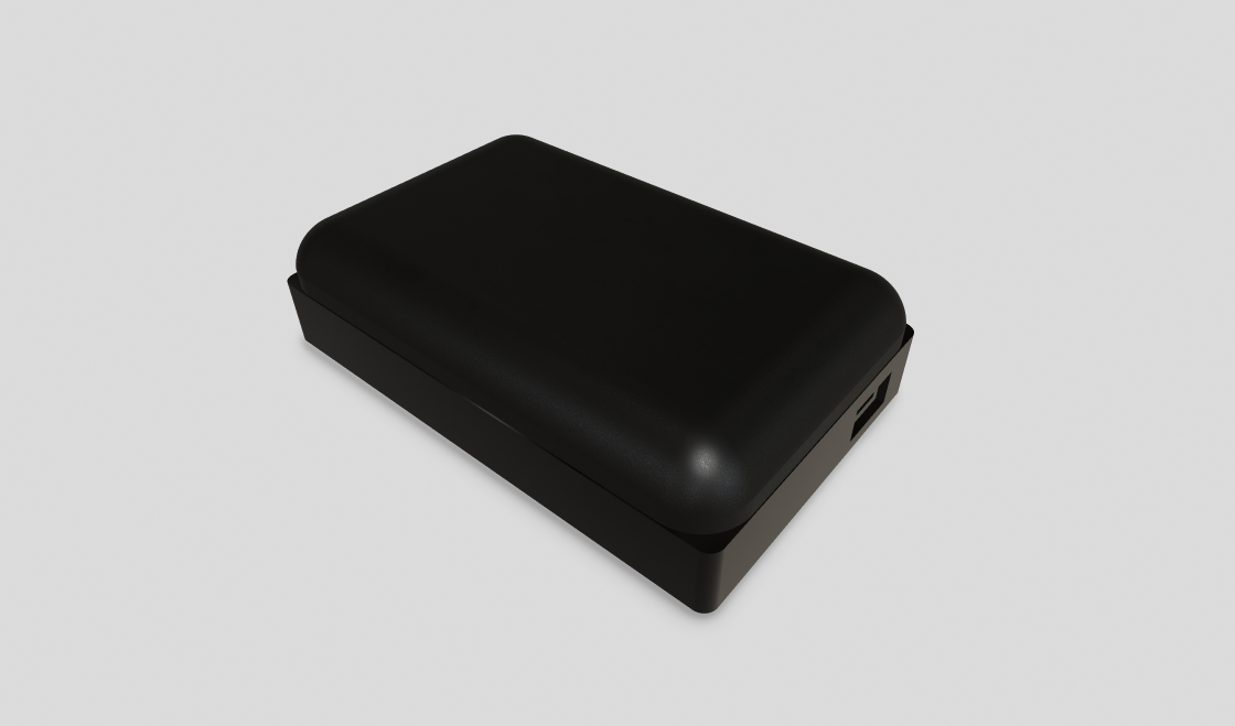
Step 4: Putting it all together.
Now that I had both the hardware and software components ready I could solder everything together. I have done some soldering in some of my other projects so this one only took about 10 minutes to setup and actually put it all together. After putting it together I discovered that I had put the wire channel on the wrong side of the PCB slot and had to use double-sided tape to hold the board in place. Other than that small hiccup everything works now and I now have a Mute Pedal toggle that I can use on all my voice calls.